|
1900 Series
Digital Antenna Monitors
PDF Brochure |
INTRODUCTION
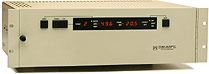
There are three different units in the 1900 Series. The basic unit
is the Model 1901.This 5 1/4 inch unit contains control/measurement
circuitry for up to 12 towers, digital display of all measurements,
local operating controls, and an interface to a remote control system.
The control/measurement circuitry for each tower is contained in a
separate module. The modules plug into the rearof the unit, and may
be easily added to an expanding station.
SIMPLIFIED OPERATION
 The
operating
controls are identical for the 1901 and 1902 models. The monitoring
system is controlled with four pushbuttons, three are located to the
left of the display and one to the right. The first pushbutton is
used to select one of three different modes. The RATIO mode displays
the true ratio of the selected tower sample as compared to the reference
sample. The AMPLITUDE mode displays the relative amplitude of the
selected tower sample. The TEST mode is used to check the calibration
of the instrument. Separate LED indicators display the selected mode. The
operating
controls are identical for the 1901 and 1902 models. The monitoring
system is controlled with four pushbuttons, three are located to the
left of the display and one to the right. The first pushbutton is
used to select one of three different modes. The RATIO mode displays
the true ratio of the selected tower sample as compared to the reference
sample. The AMPLITUDE mode displays the relative amplitude of the
selected tower sample. The TEST mode is used to check the calibration
of the instrument. Separate LED indicators display the selected mode.
The next two pushbuttons are labeled DOWN and UP. These buttons are
used to select the tower to be monitored and displayed on the front
panel LED displays. The selected tower number is shown to the right
of these pushbuttons.
Two separate four digit displays are used to indicate the amplitude
or ratio and the phase of the selected tower. The pushbutton to the
right of the digital display is used to select the PATTERN. Separate
LEDs indicate Day, Night, or a Third pattern. LEDs in the display
also indicate if the monitor is under local or external control.
PERFORMANCE FEATURES
The 1900 Series offers improved performance and simplified operation
at a lower cost than the current generation of AM-19 monitors. The
1900 Series indicates sample ratio directly with virtually no modulation
effect: independent of the power level. The 1900 Series also provides
the same phase accuracy, with automatic polarity indication, as the
industry standard AM-19.
The 1900 Series utilizes a separate control/measurement module for
each tower. The modules plug into the rear of the 1901 and 1903 units.
This feature provides a continuous readout of the ratio and phase
of each tower, simplifying the interface to a remote control device
and eliminating input switching within the monitor. The modular design
also simplifies expansion when another tower is added and eliminates
extended downtime if a spare module is available on site. The 1900
Series can accommodate up to 12 towers.
SYSTEM INTERFACING
 The
1901 and 1903 units provide a direct interface to a remote control
device. Each of the control/measurement modules (one for each tower
in the system) provides continuous analog outputs relative to the
ratio and phase for each tower. These outputs may be connected to
the telemetering inputs of the remote control device. The outputs
may also be connected to an array of meters to prove a continuous
and simultaneous display of each tower in the system. The
1901 and 1903 units provide a direct interface to a remote control
device. Each of the control/measurement modules (one for each tower
in the system) provides continuous analog outputs relative to the
ratio and phase for each tower. These outputs may be connected to
the telemetering inputs of the remote control device. The outputs
may also be connected to an array of meters to prove a continuous
and simultaneous display of each tower in the system.
External control inputs to the 1901 and 1903 units, in the form of
contact closure to ground, can switch the units to the correct pattern
and can also select the amplitude and test modes.
MODULAR CONSTRUCTION
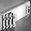 The
modular construction technique used in the 1900 Series simplifies
expansion and repair procedures. All active circuitry is contained
in modules that plug into the rear of the chassis. The unit does not
have to be removed from the rack when adding or replacing modules. The
modular construction technique used in the 1900 Series simplifies
expansion and repair procedures. All active circuitry is contained
in modules that plug into the rear of the chassis. The unit does not
have to be removed from the rack when adding or replacing modules.
|
1900
SERIES SPECIFICATIONS
Model 1901 alone or Models 1902 and 1903 together |
| Frequency Range: |
540 kHz to 1700 kHz |
| Number of Towers |
2 to 12 |
RF Inputs
|
Level range, reference: 1.5 V to 25
V RMS carrier
Level range, non-reference: 0.3 V to 25 B RMS carrier
Impedance: 50 Ohms, 72 Ohms, or Special |
| Connector |
UHF, adapters supplied to other types |
Ratio/Amplitude Display
|
Ratio range: 0 to 1.999
Ratio accuracy: ±.010
Amplitude range: 0 to 1999, scale factor and decimal position user
set |
| Patterns |
Up to 3 different reference towers;
any number of power levels, subject to the input range limits. |
| Remote Data Outputs |
DC voltage proportional to parameter,
separate outputs for each tower;
Ratio/Amplitude: 0 to 2.5 V for 0-1999 local display reading, for
any decimal position
Phase: 0 to ±2.25 V corresponding to the range of 0 to ±180.0
degrees
1000 ohms ±1ohm
Connector: Plug for each tower with screw clamp terminals |
| External Control Inputs |
For external pattern and mode selection.
Contact closure or collector to ground, +5 V open circuit. 10 mA closed
circuit. |
| Dimensions |
1901 and 1903: 19" rack panel, 5 1/4"
high, 14" deep
1902: 19" rack panel, 1 3/4" high, 6" deep |
| AC Power |
117 VAC ±10% or 234 VAC ±10%,
50-60 Hz, 50 VA maximum |
Specifications subject to change without notice.
|
- FCC authorization number: IJ3PI1900
- Digital display of ratio and phase of up to 12 towers
- Same phase accuracy as the industry standard AM-19
- Modular design simplifies expansion, reduces downtime
- Provides continuous analog outputs of all tower measurements
- Fully compatible with any standard remote control
system
- Simplified operating controls, local or external
- Measurements for up to 12 towers in 5 1/4 inch rack
height
|
|
| |
|