|
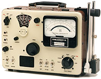
Field Strength Meter
FIM-71 VHF
PDF Brochure |
DESCRIPTION
The Model FIM-71 is a portable, laboratory quality Field Strength
Meter designed for rigorous field applications. Combining a calibrated
half-wave dipole antenna and a highly accurate tuned voltmeter with
a range of 140 dB, the FIM-71 is suitable for practically all types
of RF emission measurements in the 45 MHz to 225 MHz spectrum. The
operator can switch select wide or narrow bandwidth, peak or average
value of TV or pulse modulated signals, AM or FM demodulation, and
a meter dynamic range of either 20 dB or 60 dB. A dc analog output
voltage, proportional to the meter indication, is provided for driving
a chart recorder. A leveled output from the calibrating oscillator
is available for measuring cable insertion loss, filter response,
amplifier gain, and other signal ratio measurements. The 4-1/2 inch,
taut band, mirrored scale meter is calibrated in volts and dB for
precise measurements in field or laboratory environments.
The tuned voltmeter is a single conversion, super-heterodyne receiver
with carefully tailored sensitivity, gain, and linearity characteristics.
The RF input is double tuned and designed for minimum VSWR and maximum
out-of-band signal rejection. Uniform gain, independent of IF bandwidth,
is provided by temperature compensated RF & IF amplifiers utilizing
a combination of MOSFET, J-FET, bipolar, and monolithic integrated
circuit devices. The linear detector is followed by a logarithmic
shaping circuit which drives the meter in the LIN (20 dB) mode. In
the LOG mode the meter indication (in dB) varies linearly over a one-thousand-to-one
range of input levels. |
| FIM-71
SPECIFICATIONS |
| Frequency Range |
45 MHz-225 MHz; continuous |
| RF Input Impedance/VSWR |
50 ohms
VSWR 1.2:1, 100µV full scale and greater;
VSWR 1.5:1, 10µV full scale |
| Voltage Measurement |
1µV to 10 V rms in seven switch
selected ranges |
| Metering |
4-1/2 inch meter, mirror-backed scale,
taut band meter |
| Indication Modes |
LINear and LOGarithmic, switch selected |
| Meter Scales |
LIN mode: 1-10 (logarithmic scale)
and 0-20 dB (linear scale).
LOG mode: -20 to +40 dB (60 dB range, linear scale)
Battery voltage/External supply voltage scale. |
| Metering Detectors |
Average responding and peak responding
(for television sync pulse), switch selected |
| Receiver Bandwidths |
AM/FM: 190 kHz at -3 dB, and
TV: 450 kHz at -3 dB, switch selected |
| Absolute Accuracy |
Voltage: ±1.5 dB (LIN), ±2.0
dB (LOG); for voltage >1.5µV (AM/FM) or > 3µV (TV)
Field Strength: ±3.0 dB (LIN), ±3.5 dB (LOG) for field
strengths >1.8µV/M (AM/FM) or >3.7µV/M (TV) at 45 MHz;
>9.1 V/M (AM/FM) or >18.1µV/M (TV) at 225 MHz; using the supplied
antenna. |
| Note: These figures apply when
using the Average Detector; for the Peak Detector, noise correction
factors (supplied) are required below 10 mV |
| Relative Accuracy |
±1 dB at one frequency, for
voltage or field strength, LIN mode, for voltages >10µV,
with noise correction factors. |
| Harmonic Measurement |
Measures second harmonic field strength
of 87.5 Mhz-108 MHz signals to -80 dB for fundamental voltage less
than 100mV |
| Calibrating Oscillator |
Output switched to receiver for internal
calibration, to external output (BNC connector) of OFF. Tracks receiver
frequency when connected to receiver. |
Frequency Dial
Accuracy |
Six-turn spiral, continuous tuning,
movable cursor.
±0.5% of indicated frequency without cursor correction
±200 kHz typical, 87.5 MHz - 108 Mhz, after setting cursor
on known signal |
| RCVR Spurious Response |
Image Rejection, 55 dB typical;
IF Rejection, 100 dB typical |
| Local OSC Radiation |
45 MHz, 2µV; 225 MHz, 35µV;
typical values across 50 ohm load at RF input connector |
Demodulators
Video Frequency Response
Output Level |
AM and FM; switch selected, phone
jack (0.25") output connector
50 Hz - 100 kHz, 3 dB max. variation
4.5V p-p max. across 75-ohm load, front panel adjustable |
| Audio Monitoring |
Internal loudspeaker; headphones plug
into demodulator output jack (disconnecting speaker);
AM or FM selected by DEMOD switch; level control with disabling switch |
Record Output
Tip Contact
Ring Contact |
Two-circuit phone jack (.25")
output
DC analog of meter indication -0.8V to -8V (open circuit), 2000 ohm
source resistance
DC output from FM discriminator, @ -5 V + or -± 3 V, 10,000
ohm source resistance
(Single circuit phone plug provides tip contact output only.) |
Power Supply:
Internal Batteries
Battery Life
External Supply |
1.5 volt size "D" batteries, ten required
1500 readings or 18 hours continuous operation using Eveready No.
950 batteries (or equivalent) at 70°F
11.5 volts to 19.0 volts DC, positive ground, 120 mA, Switchcraft
No. 760 Connector (or equivalent) |
| Temperature Range |
+ 15°F to +105°F (-10°C
to +40°C) |
| Dimensions, Inches (CM) |
Without Antenna: 9.5 (24) high, 12.25
(31) wide, 7.25 (18.4) deep
With Antenna attached and retracted, 9.9 (25) high, 13.5 (34.3) wide,
7.25 (18.4) deep |
| Weight, Pounds (KG) |
20 (9.1) with batteries, antenna,
cover, cables and softcase |
Note: Values without limits
are typical only. Field strength data are with
ANT-71 Antenna. |
| Antenna Ant-71 |
| Type: |
Tunable half-wave dipole with continuously
adjustable telescoping elements. |
| Frequency Range:
|
45 Mhz - 225 MHz |
| Calibration: |
Antenna Factor data supplied based
on NIST calibration; overall error including NIST calibration uncertainty,
±.5 dB max |
| Load Impedance: |
50 ohms |
| Mounting: |
Mounts on case for hand-held measurements
at an antenna height of approx 7 ft.; has 1/4-20 threaded hole for
mounting to other masts |
Specifications subject to change without notice.
|
- Direct Reading - Volts or dB
- 45 MHz to 225 MHz, Continuous Tuning
- Peak or Averaging Detector
- Wide or Narrow IF Bandwidth
- 20 dB or 60 dB Meter Range
- AM or FM Demodulator
- Calibrated Dipole Antenna, Case Mount or Removable
- 140 dB Measurement Range (1 uB to 10 V)
- 4 1/2 inch, Mirrored Scale, Taut-Band Meter
- Front Panel Speaker
- Rugged, Portable
- Calibrated Signal Generator
OPTIONS
- AC power adapter
- unipod
- carrying case
- antenna elements and balun
- headset
|
|